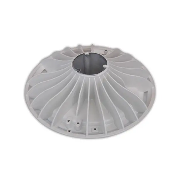
Every die casting defect has a mechanism, and every mechanism has a design or process lever that controls it. This tour of the common defects — and how a die shop that designs its own tools approaches them — will help buyers read samples intelligently and specify parts that cast cleanly.
Porosity — small voids inside the casting — comes in two families. Gas porosity is rounded, caused by air or gas entrapped as metal fills the die at speed. Shrinkage porosity is jagged, caused by metal starving as thick sections solidify and contract without feed metal. Both are influenced before the machine ever cycles: gate position and fill pattern decide how air escapes; wall uniformity decides whether sections feed or starve; venting decides whether the air that must leave, can.
Buyers should know porosity is a managed characteristic, not a binary one. Parts have functional zones (sealing faces, pressure boundaries, threaded bosses) where porosity is unacceptable and cosmetic or low-stress zones where trace porosity is harmless. Specifying those zones on the drawing — and reviewing them with the die designer — produces better parts than a blanket 'no porosity' note nobody can verify. Our high pressure die casting work is planned exactly that way: critical zones named at review, die design answering them.
A cold shut is a visible seam where two metal fronts met but failed to fuse — the metal arrived too cold, too slow, or too oxidised to marry. A misrun is its bigger sibling: a section that never filled at all. Flow marks are the cosmetic version: surface patterns recording the fill's journey, damning on a polished part and irrelevant on an internal one. All three are fill-temperature-and-speed stories, written by wall thickness, flow distance, gate design and die temperature discipline.
Thin walls far from the gate are the classic risk geometry, and they appear constantly in real designs because products want to be light. The counters are die-side (gate placement, overflow and vent design, thermal management) and part-side (local wall adjustments the review will propose). A part that will be polished and lacquer-coated — like the A380 polished and lacquer-coated casting in this range — gets its fill design reviewed with the finish in mind, because flow marks that a matte coating would hide will telegraph through polish.
Flash — the thin fin of metal escaping at the parting line — reports die fit and clamp condition; a little is trimmed as routine, a lot signals a tool that needs attention. Soldering is aluminum adhering to the die surface, tearing the casting's skin at ejection; it lives at hot spots and is fought with die cooling, coatings and release discipline. Ejector marks witness where the part was pushed out — harmless in the right places, defects on cosmetic faces, which is why ejector placement is a drawing-review topic, not a surprise at sampling.
All three are reasons tooling ownership matters. These are die-condition issues, and the fastest corrective loop is the one where the die's designers maintain the die — the structure of this factory since its mould division opened in 1996. When a buyer asks 'who holds and maintains my die, and where', they are asking about tomorrow's flash and soldering, whether they know it or not.
Drag marks, die lines, slight texture variation — die casting's cosmetic vocabulary is long, and professional buying means grading defects by consequence. On a housing's hidden interior, most surface findings are noise. On a visible, coated or polished face, the same findings are rejects. The specification habit that aligns everyone: mark cosmetic faces and acceptance expectations on the drawing, and approve a boundary sample at first article that both sides keep.
That discipline pairs with the finish plan. Powder coating forgives and hides; polishing exposes; anodizing reveals its own set of truths. Defect acceptance should always be written against the finished part, not the raw casting — the raw casting is an intermediate, and judging it by finished standards wastes everyone's inspection time.
Inspection finds defects; design prevents them. The highest-leverage moment in a casting programme is the DFM review, where wall transitions are smoothed, gates are planned, vents are given somewhere to go, critical zones are named and ejectors are placed off cosmetic faces. Every defect in this article is cheaper in that meeting than anywhere downstream.
If you are evaluating a casting — yours or a sample's — bring the questions this article arms you with: Where are my porosity-critical zones, and how does the die design answer them? Where do ejectors land? What does the fill do on my thinnest wall? A die casting supplier who enjoys those questions is the one whose castings you want; send yours through our contact form and put us to the test.
Tell us the material grade, quantity and finish you need for your project. Our engineers review every drawing for die casting, machining or stamping feasibility before quoting — no obligation.
Send Drawings for a DFM Review